Pneumatic system symbols are standardized representations used to design and troubleshoot compressed air systems. These symbols provide a universal language for engineers and technicians, ensuring clarity and efficiency in system design and operation. They are essential for creating circuit diagrams, identifying components, and understanding airflow dynamics. This section introduces the fundamental concepts and importance of pneumatic symbols in modern industrial applications.
Importance of Pneumatic Symbols in System Design
Pneumatic symbols are crucial for efficient and clear system design, ensuring universal understanding among engineers and technicians. They standardize communication, reducing errors and enhancing collaboration. Symbols provide a visual shorthand, streamlining the design process and making schematics easier to interpret. Compliance with standards like ISO 1219-1 ensures systems meet industry regulations, promoting safety and functionality. They also facilitate troubleshooting and maintenance, enabling quicker issue identification and resolution. Additionally, symbols support education by providing a consistent learning tool for new engineers. Their use ensures precise system assembly, minimizing installation errors. Overall, pneumatic symbols are vital for effective, safe, and innovative system design, fostering productivity and advancement in pneumatic technology.
Overview of Common Pneumatic Components and Their Symbols
Recognizing common pneumatic components and their symbols is essential for interpreting circuit diagrams and designing efficient systems. Key components include cylinders, actuators, compressors, directional control valves, and pressure regulators. Each component is represented by a unique symbol, such as the rectangular box for cylinders or the circular shape for compressors. Directional control valves, like 2/2-way or 5/2-way valves, are depicted with lines and arrows indicating airflow paths. Pressure regulators are shown with symbols that highlight their function of controlling air pressure. These symbols are standardized in documents like ISO 1219-1, ensuring consistency across industries. Understanding these symbols allows engineers to design, troubleshoot, and maintain pneumatic systems effectively, ensuring optimal performance and safety.

Basic Pneumatic System Components and Their Symbols
Pneumatic systems rely on essential components like cylinders, actuators, compressors, and valves. Each component is represented by standardized symbols, simplifying circuit design and troubleshooting processes universally.
Cylinders and Actuators
Cylinders and actuators are fundamental components in pneumatic systems, converting compressed air energy into mechanical motion. Pneumatic cylinders are typically represented by rectangular boxes with arrowheads indicating the direction of piston movement. Single-acting cylinders, double-acting cylinders, and rodless cylinders each have distinct symbols, reflecting their operational differences. Actuators, including linear and rotary types, are often depicted with similar notations, showcasing their role in executing specific tasks. Grippers and other specialized actuators also have unique symbols, emphasizing their functionality in handling or clamping objects. These symbols are standardized, such as in ISO 1219-1, ensuring universal understanding. Engineers rely on these representations to design and troubleshoot pneumatic circuits effectively, making them indispensable in system documentation and implementation.
Compressors and Air Supply Equipment
Compressors and air supply equipment form the heart of pneumatic systems, generating and conditioning compressed air for distribution. Compressors are symbolized as circles with internal mechanisms, indicating air compression. Air tanks, represented by cylindrical shapes, store compressed air for system stability. Filters, regulators, and dryers, often combined into a single unit, are depicted using symbols that denote air purification and pressure control. These components ensure clean, dry air at the correct pressure, crucial for optimal system performance. Their symbols in circuit diagrams highlight their role in the air supply chain, from generation to preparation. This standardized representation aids in designing efficient pneumatic systems, ensuring reliable operation across various industrial applications. Proper depiction of these symbols is vital for clear communication and effective troubleshooting.
Directional Control Valves
Directional control valves are essential components in pneumatic systems, regulating the flow of compressed air by directing it to specific parts of the system. Their symbols vary based on functionality, such as 2/2-way (two ports, two positions) or 5/2-way (five ports, two positions) valves. These symbols are standardized, often following ISO 1219-1, to ensure universal understanding. They are typically represented as squares with internal lines indicating airflow paths and valve positions. Pilot-operated valves include additional symbols for control mechanisms. Accurate representation of these valves in circuit diagrams is critical for designing and troubleshooting pneumatic systems. Their symbols simplify communication among engineers, enabling precise system configuration and operation. Proper use of directional control valve symbols ensures efficient airflow management in industrial applications.
Pressure Regulators and Relief Valves
Pressure regulators and relief valves are critical components in pneumatic systems, ensuring safe and efficient operation by controlling air pressure. Their symbols are standardized to represent their functions clearly. Pressure regulators are depicted with a rectangular body and an adjusting knob, indicating their role in maintaining consistent air pressure. Relief valves, often shown with a spring and exhaust port, symbolize their function in releasing excess pressure to prevent system overloading. These symbols are essential for designing and troubleshooting pneumatic circuits, ensuring proper pressure management. They are standardized according to ISO 1219-1, providing a universal language for engineers. Accurate representation of these valves in diagrams is vital for system safety and performance, enabling precise control of compressed air flow.
ISO 1219-1 Standard for Pneumatic Symbols
ISO 1219-1 standardizes pneumatic symbols, ensuring clarity in circuit diagrams. It covers supply lines, valve controls, and component representations, aiding in universal system design and troubleshooting.
Overview of ISO 1219-1 and Its Relevance
ISO 1219-1 is an international standard defining graphical symbols for fluid power systems, including pneumatics. It provides a unified language for engineers and technicians to design, maintain, and troubleshoot systems. The standard covers symbols for components like cylinders, valves, and pumps, ensuring consistency across industries. Its relevance lies in enhancing communication, reducing errors, and facilitating compliance with global engineering practices. By standardizing symbols, ISO 1219-1 streamlines the creation of circuit diagrams, making it easier to understand and implement pneumatic systems worldwide.
Supply and Return Lines in Pneumatic Systems
Supply and return lines are fundamental components in pneumatic systems, represented by distinct symbols in circuit diagrams. These lines are responsible for transferring compressed air from the compressor to components and returning exhaust air to the atmosphere. The supply line is typically depicted with an arrow indicating the flow direction, while the return line is shown with a similar arrow but in the opposite direction. Proper differentiation between these lines is crucial to ensure system functionality and avoid malfunctions. ISO 1219-1 standardizes these representations, ensuring clarity and consistency in pneumatic system design. Accurate depiction of supply and return lines is essential for engineers and technicians to understand airflow dynamics and maintain system efficiency effectively.
Valve Controls and Their Symbolic Representation
Valve controls are pivotal in pneumatic systems, directing airflow efficiently. Their symbolic representation is standardized, ensuring clear communication. Common symbols include 2/2-way, 3/2-way, and 5/2-way valves, each indicating different control functions. These symbols are crucial for circuit diagrams, enabling engineers to understand valve operations and system behavior. ISO 1219-1 defines these representations, simplifying design and troubleshooting. Accurate use of these symbols ensures proper system functionality and safety, making them indispensable in pneumatic applications.

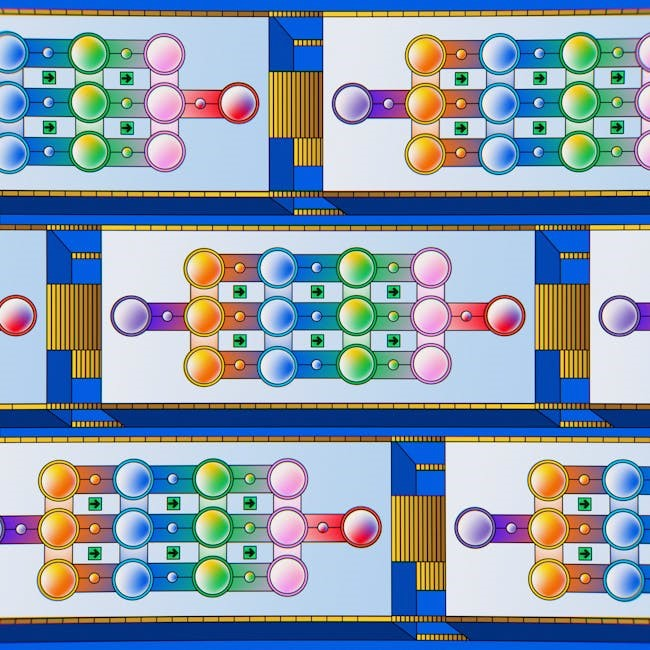
Pneumatic Circuit Diagrams and Symbol Applications
Pneumatic circuit diagrams visualize system components and their interactions using standardized symbols. These diagrams are essential for designing, troubleshooting, and maintaining compressed air systems efficiently.
Understanding Circuit Diagram Layouts
Pneumatic circuit diagrams are detailed visual representations of system components and their connections. These layouts use standardized symbols to depict compressors, valves, cylinders, and other elements. Understanding the arrangement is crucial for designing efficient systems. Supply and return lines are typically shown in specific colors or patterns for clarity. The diagrams also illustrate airflow direction, control logic, and sequence of operations. Proper interpretation ensures safe and effective system operation. ISO 1219-1 standards often guide the creation of these layouts, ensuring consistency across industries. By mastering circuit diagrams, engineers can troubleshoot issues, optimize performance, and integrate new components seamlessly. Practical examples and reference materials, such as PDF guides, are essential for learning and applying these principles effectively.
Common Symbol Systems and Conventions
Standardized symbol systems are vital for consistency in pneumatic circuit diagrams. ISO 1219-1 provides a universal framework for representing components like valves, cylinders, and compressors. Symbols are categorized based on function, such as directional control valves (e.g., 2/2 or 5/2-way) and pressure regulators. Color coding and line styles differentiate supply and return lines, ensuring clarity. These conventions are widely adopted across industries to avoid confusion. Resources like PDF guides from manufacturers (e.g., SMC, Kuhnke) offer detailed libraries of symbols. Adhering to these standards ensures that diagrams are easily interpretable by engineers worldwide. Proper use of symbols and conventions is essential for accurate system design, troubleshooting, and maintenance, promoting efficiency and safety in pneumatic applications.
Practical Examples of Symbol Usage
Practical examples of pneumatic symbol usage are essential for understanding their application in real-world systems. For instance, symbols for cylinders, directional control valves, and pressure regulators are commonly used in circuit diagrams. A typical example is a pneumatic actuator system, where symbols for compressed air supply, directional control valves, and cylinders are interconnected to illustrate airflow and functionality. Manufacturers like SMC and Kuhnke provide detailed PDF guides with symbols for components such as 2/2-way valves, air tanks, and filters. These symbols are applied in industrial automation, robotics, and machinery design. Practical examples also include troubleshooting diagrams, where symbols help identify faulty components. Resources like ISO 1219-1 and component catalogs offer extensive libraries of symbols, enabling engineers to design and maintain pneumatic systems efficiently. These examples demonstrate how symbols streamline system design and operation.

Advanced Pneumatic System Symbols

Advanced pneumatic symbols represent specialized components like proportional valves, servo valves, and complex control systems. These symbols are used in industrial automation and precision engineering applications, ensuring detailed system representation and control.
Specialized Valves and Their Symbols
Specialized valves in pneumatic systems include proportional valves, servo valves, and pilot-operated valves. These components are represented by unique symbols that denote their functions, such as flow control, pressure regulation, and directional changes. Proportional valves, for instance, use symbols that indicate variable flow rates, while servo valves are depicted with feedback mechanisms. Pilot-operated valves are shown with separate control lines, highlighting their operation. These symbols are crucial for designing complex systems, ensuring precise control and efficiency. They are detailed in resources like the Kuhnke Pneumatic Symbols PDF and other industry standards, providing clear guidelines for engineers. Understanding these symbols is essential for maintaining and optimizing advanced pneumatic circuits.
Complex Components and Their Representation
Complex components in pneumatic systems, such as multi-function valves, custom manifolds, and integrated control modules, are represented by detailed symbols. These symbols often combine multiple elements to illustrate the component’s functionality. For example, a multi-function valve may include symbols for flow control, pressure regulation, and directional changes. Custom manifolds are depicted with interconnected ports and flow paths. These representations ensure clarity in system design and troubleshooting. Resources like the Kuhnke Pneumatic Symbols PDF provide comprehensive libraries of these symbols, adhering to standards like ISO 1219-1. Understanding these symbols is critical for diagnosing and maintaining advanced pneumatic systems effectively.
Symbol Systems for Industrial Automation
In industrial automation, pneumatic symbol systems play a crucial role in designing and integrating automated control systems. These symbols are standardized to ensure consistency across designs and facilitate communication among engineers. Symbols for components like solenoid valves, sensors, and actuators are detailed to reflect their roles in automation. The ISO 1219-1 standard provides guidelines for representing these symbols, ensuring compatibility with industrial automation protocols. Resources like the Kuhnke Pneumatic Symbols PDF offer comprehensive libraries of these symbols, aiding in the creation of precise circuit diagrams. By adhering to these standards, engineers can efficiently design and troubleshoot automated pneumatic systems, ensuring optimal performance and reliability in industrial applications.

Resources for Pneumatic System Symbols
Downloadable PDFs like the Kuhnke Pneumatic Symbols PDF and resources from Ross Controls offer detailed libraries of pneumatic symbols. These documents provide standardized representations for components, ensuring accuracy in system design and troubleshooting.
PDF Downloads and Reference Materials
Several organizations offer PDF downloads of pneumatic system symbols, such as the Kuhnke Pneumatic Symbols PDF and Ross Controls’ reference materials. These documents provide comprehensive libraries of standardized symbols for components like cylinders, valves, and compressors. They serve as essential tools for engineers and technicians, ensuring accurate system design and troubleshooting. The ISO 1219-1 standard is frequently included in these resources, offering detailed guidelines for symbol usage. By downloading these materials, professionals can access clear diagrams and descriptions, facilitating the creation of pneumatic circuit diagrams and maintaining consistency across projects. These resources are indispensable for both educational and industrial applications, promoting efficiency and precision in pneumatic system development.

Online Tools for Symbol Design and Diagramming
Online tools like SMC Pneumatic’s symbol libraries and ISO-compliant diagramming platforms simplify the creation of pneumatic system diagrams. These tools offer customizable templates, drag-and-drop functionality, and real-time collaboration features. They allow users to design and share circuit diagrams efficiently, ensuring compliance with ISO 1219-1 standards. Many platforms provide pre-designed symbols for components like cylinders, valves, and compressors, streamlining the design process. Additionally, these tools often integrate with industrial automation software, enabling seamless implementation of designs. By leveraging these resources, engineers and technicians can create accurate and professional pneumatic system diagrams, enhancing productivity and precision in system development and troubleshooting.
Recommended Standards and Documentation
ISO 1219-1 is the primary standard for pneumatic system symbols, providing a comprehensive guide for graphical representations in circuit diagrams. It ensures consistency and clarity in system design and troubleshooting. Documentation like PDFs from Kuhnke and Ross Controls offer detailed symbol libraries and component descriptions. These resources are essential for engineers and technicians to accurately interpret and design pneumatic systems. Additionally, standards like ISO 1219-1 cover supply and return lines, valve controls, and component enclosures, ensuring a universal graphical language for fluid power systems. Adhering to these standards is crucial for maintaining compatibility and efficiency in industrial automation and system integration. Proper documentation and standards ensure that pneumatic systems are designed and operated safely and effectively.
Pneumatic system symbols are essential for efficient and safe system design. Understanding these symbols, as outlined in ISO 1219-1, ensures clarity and precision in compressed air applications.

Key Takeaways from Pneumatic System Symbols
Understanding pneumatic system symbols is crucial for designing and maintaining compressed air systems. These symbols, standardized in ISO 1219-1, provide a universal language for engineers and technicians. Key components like cylinders, compressors, and directional control valves are represented by distinct symbols, ensuring precise communication. Circuit diagrams rely on these symbols to illustrate airflow, connections, and component functions. Mastery of these symbols enhances efficiency in troubleshooting and system optimization. They also facilitate compliance with industry standards, reducing errors and improving safety. By familiarizing oneself with pneumatic symbols, professionals can streamline workflows and ensure reliable system performance.
Future Trends in Pneumatic Symbol Standardization
The future of pneumatic symbol standardization lies in harmonizing global practices and integrating digital tools. ISO 1219-1 will continue to play a central role, with updates to accommodate emerging technologies. Digital libraries and software for symbol design will become more prevalent, streamlining system creation. Standardization efforts will focus on reducing variability across industries and enhancing interoperability. Automation and smart technologies will drive demand for standardized symbols in industrial IoT applications. Education and training programs will emphasize symbol literacy to meet industry needs. Sustainability and energy efficiency will also influence symbol development, ensuring systems are optimized for performance. These trends will ensure pneumatic symbols remain a cornerstone of fluid power system design and operation.